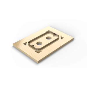
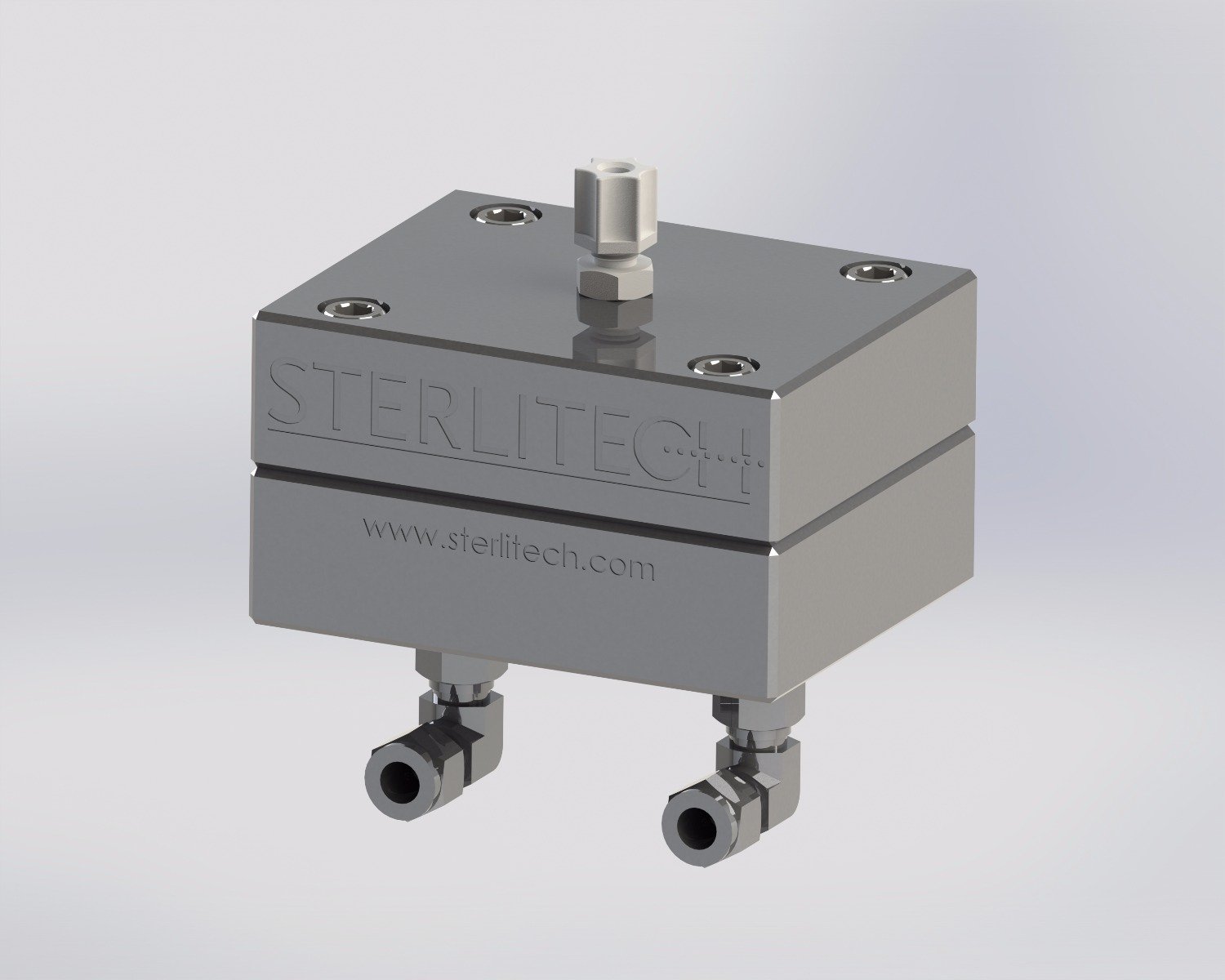
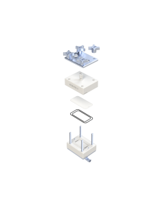
Steel Rule Die, CF042
Steel Rule Die for cutting membrane coupons to fit CF042 test cells.
 Powered by Bioz
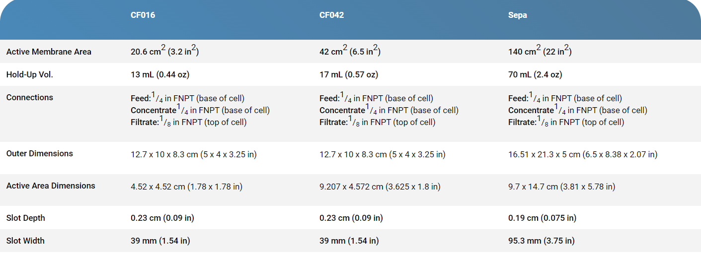
Specifications
|
|
CF016 |
CF042 |
Sepa |
|---|---|---|---|
|
Active Membrane Area |
20.6 cm2 (3.2 in2) |
42 cm2 (6.5 in2) |
140 cm2 (22 in2) |
|
Hold-Up Vol. |
13 mL (0.44 oz) |
17 mL (0.57 oz) |
70 mL (2.4 oz) |
|
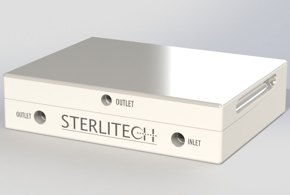
Connections |
Feed:1/4 in FNPT (base of cell) |
Feed:1/4 in FNPT (base of cell) |
Feed:1/4 in FNPT (base of cell) |
|
Outer Dimensions |
12.7 x 10 x 8.3 cm (5 x 4 x 3.25 in) |
12.7 x 10 x 8.3 cm (5 x 4 x 3.25 in) |
16.51 x 21.3 x 5 cm (6.5 x 8.38 x 2.07 in) |
|
Active Area Dimensions |
4.52 x 4.52 cm (1.78 x 1.78 in) |
9.207 x 4.572 cm (3.625 x 1.8 in) |
9.7 x 14.7 cm (3.81 x 5.78 in) |
|
Slot Depth |
0.23 cm (0.09 in) |
0.23 cm (0.09 in) |
0.19 cm (0.075 in) |
|
Slot Width |
39 mm (1.54 in) |
39 mm (1.54 in) |
95.3 mm (3.75 in) |
| Product | Material | Maximum Bolts Torque Setting (in-lbs) | Maximum Fittings Torque Setting (in-lbs) | Max Pressure | Max Temperature |
|---|---|---|---|---|---|
 CF016D |
Acetal (Delrin) | 60 | 25 | 69 bar (1000 psig) | 82°C (180°F) |
 CF016SS |
316 Stainless Steel | NA | 25 | 69 bar (1000 psig) | 150°C (302°F) |
 CF016P |
Virgin PTFE | 15 | 25 | 27.6 bar (400 psig) | 260°C (500°F) |
 CF016A |
Acrylic | 45 | 25 | 27.6 bar (400 psig) | 88°C (190°F) |
 CF042D |
Acetal (Delrin) | 60 | 25 | 69 bar (1000 psig) | 82°C (180°F) |
 CF042SS |
316 Stainless Steel | NA | 25 | 69 bar (1000 psig) | 150°C (302°F) |
 CF042P |
Virgin PTFE | 15 | 25 | 27.6 bar (400 psig) | 260°C (500°F) |
 CF042A |
Acrylic | 45 | 25 | 27.6 bar (400 psig) | 88°C (190°F) |
 CF042H |
Hastelloy™ | 70 | 25 | 69 bar (1000 psig) | 150°C (302°F) |
 Sepa CF |
316 Stainless Steel | NA | 25 | 69 bar (1000 psig) | 150°C (302°F) |
 AC Sepa |
Acrylic | 45 | 25 | 15.2 bar (220 psig) | 88°C (190°F) |
HAS Sepa CF |
Hastelloy™ | 70 | 25 | 69 bar (1000 psig) | . |
 Titanium Sepa |
Titanium | 139 bar (2000 psig) | 177°C (350°F) |
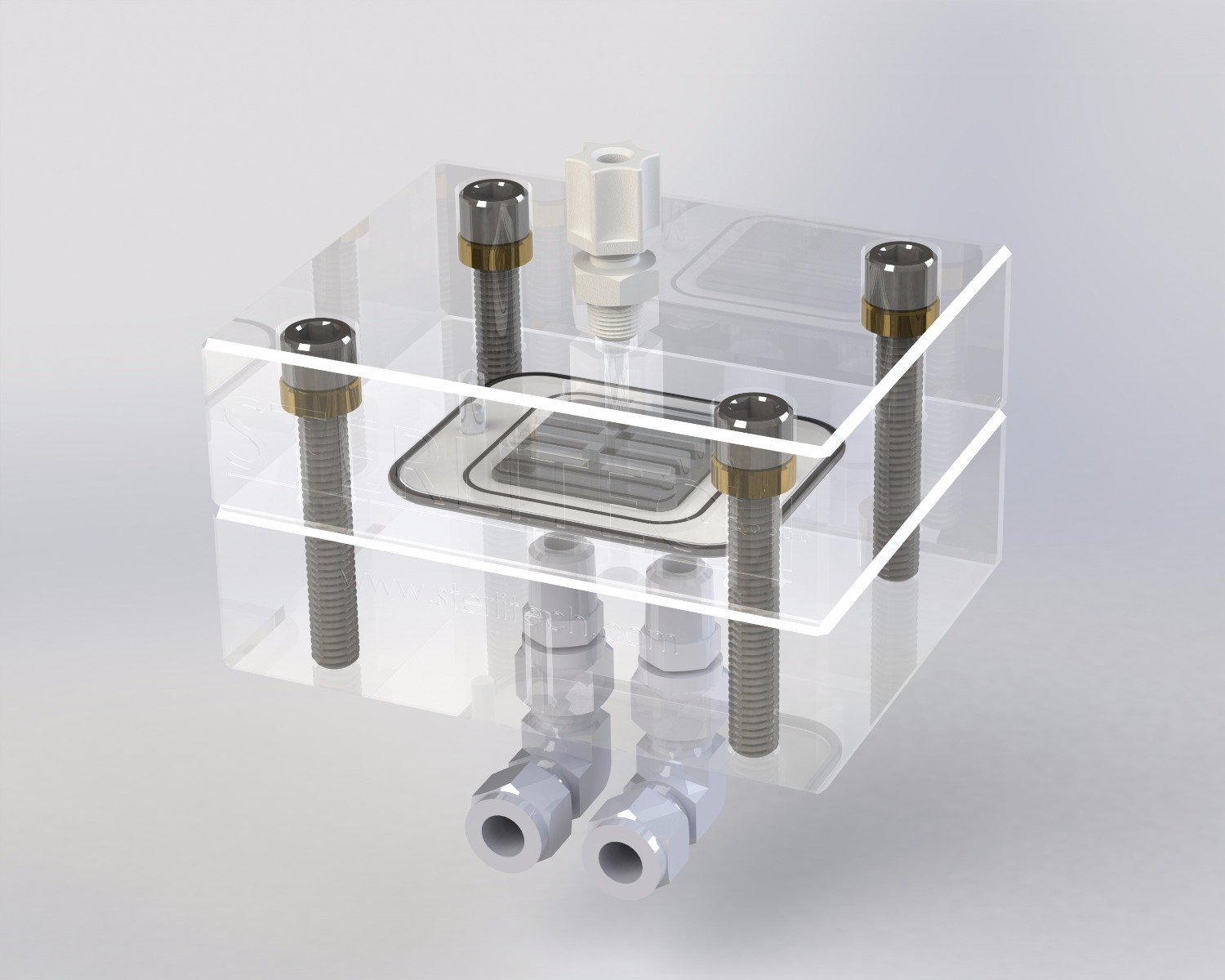
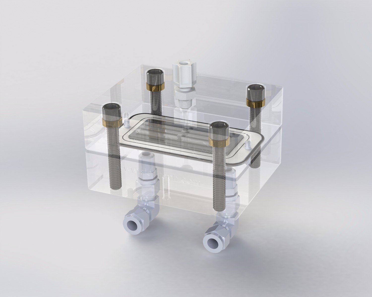
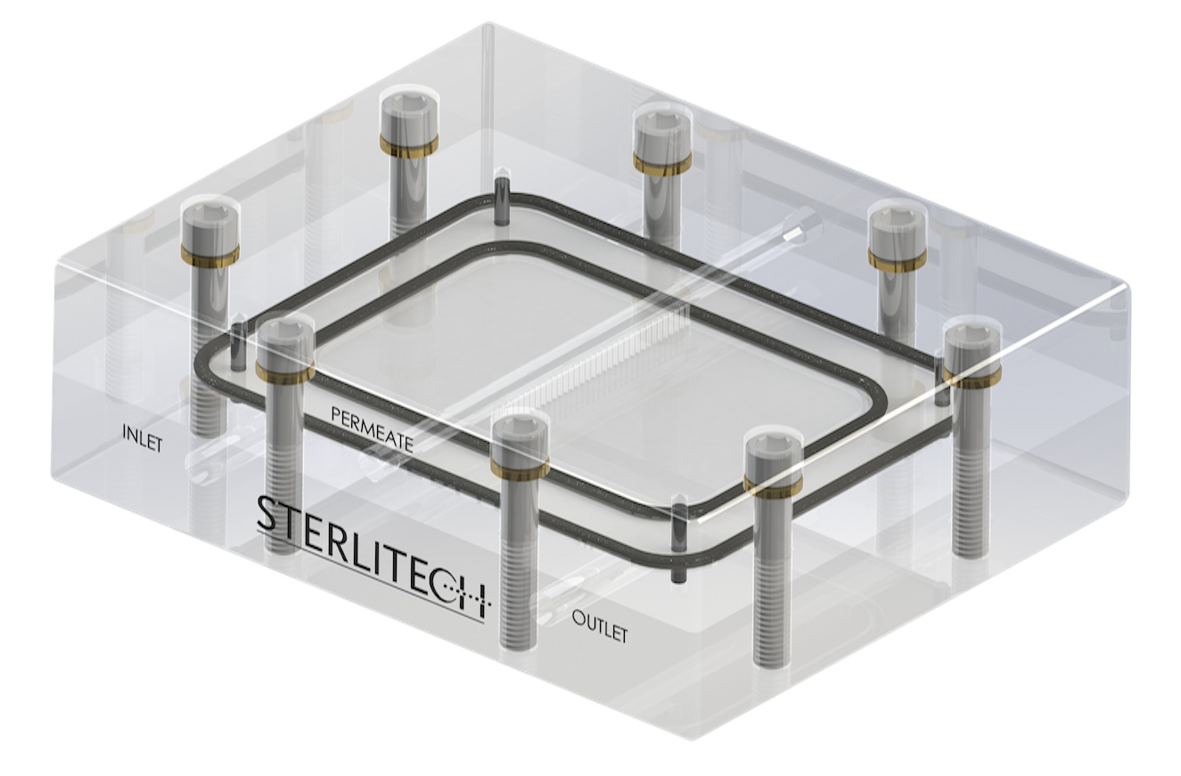
Animation
Cross/tangential flow test cells are typically used in membrane applications such as :
- Membrane test and quality assurance
- Biological or biopharmaceutical processing
- Concentration of fruit juices and extracts
- Food and beverage processing
- Desalination of brackish water or seawater
- Purification of rinse water in electroplating tanks
- Municipal or industrial water and wastewater purification
Check out other related products below!
 Frequently Asked Questions
Q: Are your PP spacers FDA compliant?
Yes, our Bi-Planar Feed Spacer Mesh is extruded from FDA compliant polypropylene.
Q: What is the recommended flow rate for the CF cells?
Please refer to the following diagram to examine recommended feed flow rates for the crossflow cell you are working with.
Q: Why is the flat sheet membrane I'm using measuring a flux value less than the published flux value?
Flow characteristics for a spiral element and flat sheet membrane are significantly different and are really only comparable on a qualitative basis. Variability in the membrane manufacturing process, differences in water composition, test procedures, and test equipment, used in a factory, laboratory, or elsewhere, will impact water flux results.
Reference: Understanding Variation of Experimental Flux and Rejection
Q: What is the recommended cross flow velocity range for the SEPA CF or CF042 cells?
Cross flow velocity affects the hydrodynamic conditions in the system and therefore affects the rate of fouling. If the objective of the experiment is to mimic the hydrodynamic conditions in commercially available spiral wound elements it is recommended to stay in the range recommended by the manufacturers. Please contact Sterlitech for more information.
If the objective of the experiment is to shed light into the effect of cross flow velocity on the membrane performance/fouling, the optimum range of cross flow velocity should be identified experimentally.
Q: What is the recommended flow rate for the CF cells?
lease refer to the following diagram to examine recommended feed flow rates for the crossflow cell you are working with.
Q: What is the application of feed spacer?
Feed spacers are used to mimic the hydrodynamic conditions of large-scale membrane modules by changing the flow regime and creating turbulence inside the feed channel of our membrane test cells.
For more information on feed spacers incorporated into our test cells, please visit here.
Q: What is the thickness of feed spacers (17, 31, 47, and 65 mil diamond spacers)?
The “mil” measurement represents 1/1000th of an inch. Therefore, the thicknesses are 0.017, 0.031, 0.047, 0.065 inches (17, 31, 47, and 65 mil, accordingly).
Q: How do I optimize my crossflow test cell operating conditions for maximum permeate flux?
Most separations and flux through membranes are controlled by the nature of the fluid. For salt rejecting membranes (RO and NF), the dominant variables are operating pressure and osmotic pressure (a solute concentration-dependent property which reduces net operating pressure with increased solute concentrate).
Generally, permeate flux increases as the operating pressure increases; however, due to physical limitations of membranes, there is a practical limit above which increasing the operating pressure provides little or no flux increase. The fluid velocity across the membrane, controlled by the feed pump rate and concentrate control valve, is another important operating parameter. As the fluid velocity increases, the amount of mixing of the feed solution in the fluid layer directly above the membrane surface increases. The removal of fluid through the membrane (permeate) results in accumulation of rejected solutes in this layer, referred to as the boundary layer.
The accumulation of solutes in the boundary layer can contribute a significant resistance to permeate flux through the membrane and is often the factor most limiting permeate flux. Increasing the feed solution velocity across the membrane and using turbulence promoting foulant spacers, provides the optimal combination for boundary layer mixing to mitigate solute accumulation. However, considerations of energy expenditures and mechanical stress limitations of the membrane and the test cell system result in practical limitations for crossflow velocity. To find maximum permeate flux, we set the feed flow (and consequently the crossflow velocity) to a maximum practical rate and increase the operating pressure incrementally while monitoring the flux output.
Typically, a given operating pressure can be found that will yield maximum permeate flux specific to the feed solution and feed flow. If the feed is recirculated and the solute concentration changes, then the optimal operating pressure may change and typically decreases as solute concentration increases unless the osmotic pressure becomes significant. For systems operated with recirculating feed, it may be more optimal to operate at a pressure somewhat lower than the maximum pressure initially determined and may result in greater total permeate flux over time.
Q: What is the application of permeate carriers?
Permeate carriers, also known as “permeate water carriers” are aids that are installed between two layers of the flat sheet membranes in a spiral wound element. The main application of this collection layer is to prevent the membrane layers from closing in on each other under high-pressure operations and also facilitate the collection of permeate water.
Q: Is there a difference in membrane rejection and permeate flux for a crossflow test cell operated continuously versus being operated in intervals?
Q. Is there a difference in membrane rejection and permeate flux for a crossflow test cell operated continuously versus being operated in intervals?
A. Yes, there may be a difference in membrane rejection and permeate flux, at least initially during the operating intervals. At startup, there is a period of membrane conditioning that occurs as a result of mechanical compression.
This conditioning influences the rejection and permeate flux and is to some extent reversible when the operating pressure is relieved.
Consequently, there is a period of membrane conditioning that occurs every time the system is restarted. For sufficiently long operating intervals, the rejection and permeate flux will approach those for continuous operation.
Q: What are the available materials of construction for the Sterlitech crossflow test cells?
The Sterlitech bench-scale crossflow test cells are available in a variety of materials to suit most applications:
- Stainless Steel
- PTFE
- HastelloyTM
- Delrin (natural acetal copolymer)
- Acrylic
Addtionally, there are a variety of available o-ring seals including Buna-N, EPDM, Viton, FEP encapsulated Viton, and FFKM (Markez).
Q: Can I operate a crossflow test cell without a foulant spacer?
Q. Can I operate a crossflow test cell without a foulant spacer?
A. Depending on the feed pressure and crossflow velocity, operating a crossflow test cell without a foulant spacer may cause the membrane to become wrinkled and damaged, and is not recommended.
Typically, a foulant spacer with the same thickness as the feed channel is used. A foulant spacer thinner than the feed channel can be used in combination with a shim (or shims) of appropriate thickness.
Q: Should I be concerned if the foulant spacer leaves an imprint on the membrane?
In most cases, a foulant spacer imprint on the membrane is normal and not a cause for concern. Light impressions can occur due to normal compression during operation and do not necessarily indicate damage.
However, you should verify spacer thickness to ensure the foulant spacer (or spacer + shim combination) is not thicker than the feed channel. If the spacer is too thick, it can over-compress the element and risk damaging the membrane, reducing performance and element life.
Q: How do I distinguish between the low foulant (34ml) feed spacer and the high foulant (68ml) feed spacer when I hold them in my hands?
You can usually tell the low foulant (34 mL) and high foulant (68 mL) feed spacers apart by their cell pattern, stiffness, and surface texture:
Low foulant (34 mL) feed spacer:
Has smaller square openings
Feels lighter and more flexible (bends easier in your hands)
Not as stiff as the medium/high foulant styles
High foulant (68 mL) feed spacer:
Has a corrugated, ridged texture (similar to cardboard)
Typically has no punched holes
Feels stiffer and thicker overall
Tip: If you have both on hand, compare how easily each piece flexes—the low foulant spacer will bend noticeably easier, while the high foulant spacer holds its shape due to the corrugation.
Q: Is the 17mil low foulant spacer the same as the 17mil permeate carrier? Can the permeate carrier be used as a foulant spacer?
Q. Is the 17mil low foulant spacer the same as the 17mil permeate carrier? Can the permeate carrier be used as a foulant spacer?
A. No, the foulant spacer and the permeate carrier are not the same. The foulant spacer is designed to accommodate particulate in the feed stream and to enhance the crossflow action near the membrane surface. Since there is essentially no particulate in the permeate stream, the permeate carrier is optimized to provide maximum support to the membrane without concern for accommodating particulate. Consequently, the permeate carrier should not be used as a foulant spacer.
Q: In the instruction manual for the Sepa CF, mesh and tubular foulant spacers are mentioned. What is the difference?
Q. In the instruction manual for the Sepa CF, mesh and tubular foulant spacers are mentioned. What is the difference?
A. The 31 mil low foulant spacer and the 47mil medium foulant spacer have a mesh design with discrete openings.
The 65mil high foulant spacer has a tubular or corrugated, design without discrete openings.
The tubular design is less likely to be fouled by feed streams with elevated particle loading.
Q: Can I reuse flat sheet membranes after they have been removed from a crossflow test cell?
Yes, you may attempt to reuse flat sheet membranes. However, you may find it difficult to achieve a leak free seal. The cell body o-rings necessarily compress the membrane during installation and the physical action of separating the membrane from the o-rings during removal may cause damage. This damage can impede that ability to achieve a leak free seal when the membrane is reused.
Q: How do I install/remove permeate fittings or other plastic NPT fittings?
Sterlitech recommends to install all plastic fittings by hand using PTFE tape. If a plastic NPT or compression fitting starts to leak during operational testing, tighten the fitting carefully until the leaking stops. Excessive tightening may break the fitting or damage other components.
If the fittings is broken and stuck in the cell top, use a spiral flute extractor bit or similar tool to release the portion of the fitting in the cell top. If the cell top becomes cracked from removal efforts, a replacement can be purchased.
Q: What are the differences between the crossflow test cells and the Sterlitech HP4750 stirred cell?
Sterlitech crossflow test cells (Sepa® CF, CF042, and CF016) operate in true crossflow filtration mode, meaning the feed flows tangentially across the membrane and produces both a permeate stream and a concentrate (retentate) stream. These systems allow continuous operation, with user-controlled pressure and crossflow rate, and enable ongoing sampling from both streams during testing.
The HP4750 Stirred Cell, by comparison, is a sealed batch filtration device (up to 300 mL feed volume) typically pressurized with compressed gas. It runs in normal-flow (dead-end) mode and does not have a concentrate stream. A stir bar helps reduce concentration polarization and simulates crossflow-like mixing at the membrane surface, but it is not true crossflow.
Q: What is the proper orientation for installing flat sheet membranes in the crossflow test cells?
For supported crossflow membranes, the membrane active side (smooth side) should be facing the feed stream and the support side (rough side) should be facing the permeate stream. For the Sterlitech Sepa CF, CF042, and CF016 test cells, the membrane side (smooth side) would face down toward the feed stream.
Q: How do I calculate the Reynolds number for the feed flow in a crossflow test cell?
The Reynolds number is a dimensionless number that is related to the ratio of inertial forces to viscous forces experienced by a fluid for given flow conditions. The Reynolds number can be used to predict whether flow conditions result in a laminar or turbulent flow.
In theory, the cross section area of the test cell feed channel can be used to calculate the Reynolds number for the feed flow. In practice, it is very difficult to calculate the Reynolds number because of the complex geometry of the foulant spacer occupying the feed channel. There are empirical methods to estimate the Reynolds number by characterizing the relationship between feed flow and differential pressure.
Please contact us at [email protected] if you need assistance.
Q: What is GFD?
GFD is an abbreviation for gallons per square foot per day. It is a common unit of measure for membrane permeate flow.
Q: I have noticed that the flat sheet membranes come in sizes described as CF016, CF042, and Sepa CF. What are these sizes?
Q: Could the filter cloth of industrial filters be used in the Sepa filtrations units, after cutting it to proper size?
Q. Could the filter cloth of industrial filters be used in the Sepa filtrations units, after cutting it to proper size?
A. The Sepa CF can potentially work for any media that can be fitted into the chamber.
One thing that could be an issue for some types of filter media is whether or not a sufficient seal is made between the O-ring and the media. For membranes, this is not a problem because membranes have a relatively smooth surface, which affords good mechanical seal when pressed together. A large fiber woven material, for example, may need to be modified or filled with some type of potting compound to level the surface in order to get a non-bypass seal.
Q: What is the application of shims?
During high-pressure filtration processes, the membrane sheet inside the cell may deflect outwards into the feed channel. This occurs due to variations in pressure during operation. This movement can cause rubbing against O-rings which can result in abrasion, possibility rupture, in the membrane sheet. Therefore, a piece of material (shim) can also be placed between the membrane layer and the test cell to take up the free space and help to prevent movement.
For more information on shims incorporated into our test cells, please visit here.
Q: What are the torque settings for the CF042 and Sepa CF Cells?
Q: What are the torque settings for the CF042 and Sepa CF Cells?
A: Best practices for plumbing of polymer (Acrylic, Delrin, and PTFE cells) CF042 cells, include the use of PTFE tape properly installed on 1/4npt threaded coupling, and the use of a light coat of PTFE-based pipe thread sealant, then the coupling needs to be seated in the base of the cell using the following torque settings:
- Delrin- 60 inch pounds
- Acrylic -70 inch pounds
- PTFE -15 inch pounds OR until the fitting "shoulders" out on the base of the CF042 cell*
*extreme caution should be used to assure that the fitting is not started incorrectly (cross-threaded). In normal installation, the fitting should easily turn in several turns without tooling (by "hand") before using the torque wrench.
Q: What fluid do I use in my Hydraulic hand pump for my Sepa CF?
Mobil DTE 24 hydraulic oil or equivalent.
Q: What is the pore size for the sintered stainless steel membrane support in the CF016 and CF042 test cells?
Q: What is the pore size for the sintered stainless steel membrane support in the CF016 and CF042 test cells?
A: The pore size of the sintered stainless steel membrane support is approximately 20 microns.