Sartorius Polyethersulfone (PES) Vivaflow 50 Cross Flow Cassettes, 3kDa, 2/pk
Details
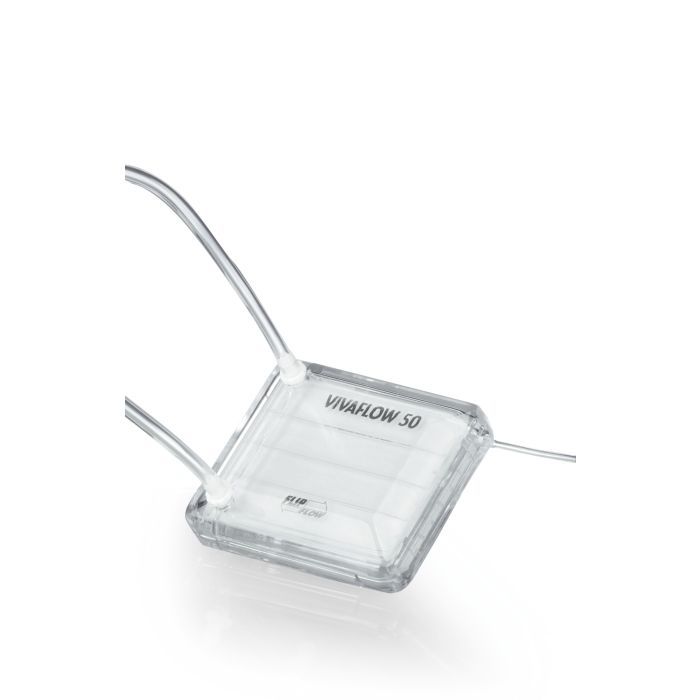
Vivaflow® 50 is a disposable and ready-to-use crossflow cassette for filtration and concentration of samples from 100/Pk ml to 3 l. The membrane surface per device is 50 cm². One pack contains two devices and comes with all necessary accessories for running two devices with a laboratory pump and a size 16 pump head. For speeding up the concentration and increasing the volume throughput. si x cassettes can be connected. Optimally suited for applications like cell culture supernatant concentration. virus concentration and water concentration e.g. in fish breading facilities. this economical product offers a standard of ease of use. reliability and fle x ibility unrivalled by any laboratory filtration system in the market. The thin-channel. flip-flow recirculation path of the modules provides high crossflow velocities with minimum pump speed requirements. A single 50 cm² module typically reduces 500 ml to 15 ml in less than 50 min. Nearly total recovery of the concentrate is achieved with a single rinse. Up to si x of the unique interlocking modules can be connected for easy scale up resulting in a capacity of several liters. Vivaflow® 50 is intended for single use. All accessories for sample concentration. e x cept a peristaltic pump with a pump head for size 16 tubing. are included in the package. A 500 ml sealed diafiltration reservoir can be added to the system for rapid and convenient buffer e x change. Equipment required The standard Vivaflow® 50 package comes with two cassettes. tubing. flow restrictor. one series interconnector and high pressure pump tubing. All you need is a peristaltic pump with a pump head capable of handling 6.4 mm OD tubing (size 16). Running more than two Vivaflow® 50 devices in parallel and series For speeding up the concentration. as many as si x Vivaflow® 50 cassettes can easily be connected using 2 T-connectors for connecting 2 Vivaflow® cassettes at the inlet and at the outlet and series interconnectors for connecting the devices inbetween. A pressure indicator needs to be built in the inlet for optimal control. High flow rate and recovery Clear housing for process monitoring Ready to use single cassettes Easy set up of multiple cassettes Economical and disposable product Unique in its performance A single 50cm² module will typically reduce 500 ml to less than 15 ml in under 50 minutes. Less than 10/Pkml minimum system recirculation for highest concentrations. Less than 1.5 ml non recoverable hold up volume. Near total recoveries achievable with a single 10/Pkml rinse. Performance Characteristics Time to concentrate up to 20 x (min.) at 3 bar inlet pressure. 20°C Single device Three devices Solute recovery % 250 ml start vol. min. 1 L start vol. min. Direct 10/Pkml rinse BSA 1.0 mg/ml (66.000 MW) 5.000 MWCO PES 34 49 96 % 99 % 10.000 MWCO PES 22 32 94 % 99 % 30.000 MWCO PES 22 32 92 % 99 % 50.000 MWCO PES 20 29 92 % 98 % γ Globulins 1.0 mg/ml 100/Pk.000 MWCO PES 43 62 92 % 98 % 100/Pk.000 MWCO RC 40 58 92 % 98 % Yeast 1.0 mg/ml (S.Cerevisiae) 0.2 μm PES 33 47 92 % 98 %
 Frequently Asked Questions
Q: How do I optimize my crossflow test cell operating conditions for maximum permeate flux?
Most separations and flux through membranes are controlled by the nature of the fluid. For salt rejecting membranes (RO and NF), the dominant variables are operating pressure and osmotic pressure (a solute concentration-dependent property which reduces net operating pressure with increased solute concentrate).
Generally, permeate flux increases as the operating pressure increases; however, due to physical limitations of membranes, there is a practical limit above which increasing the operating pressure provides little or no flux increase. The fluid velocity across the membrane, controlled by the feed pump rate and concentrate control valve, is another important operating parameter. As the fluid velocity increases, the amount of mixing of the feed solution in the fluid layer directly above the membrane surface increases. The removal of fluid through the membrane (permeate) results in accumulation of rejected solutes in this layer, referred to as the boundary layer.
The accumulation of solutes in the boundary layer can contribute a significant resistance to permeate flux through the membrane and is often the factor most limiting permeate flux. Increasing the feed solution velocity across the membrane and using turbulence promoting foulant spacers, provides the optimal combination for boundary layer mixing to mitigate solute accumulation. However, considerations of energy expenditures and mechanical stress limitations of the membrane and the test cell system result in practical limitations for crossflow velocity. To find maximum permeate flux, we set the feed flow (and consequently the crossflow velocity) to a maximum practical rate and increase the operating pressure incrementally while monitoring the flux output.
Typically, a given operating pressure can be found that will yield maximum permeate flux specific to the feed solution and feed flow. If the feed is recirculated and the solute concentration changes, then the optimal operating pressure may change and typically decreases as solute concentration increases unless the osmotic pressure becomes significant. For systems operated with recirculating feed, it may be more optimal to operate at a pressure somewhat lower than the maximum pressure initially determined and may result in greater total permeate flux over time.
Q: Is there a difference in membrane rejection and permeate flux for a crossflow test cell operated continuously versus being operated in intervals?
Q. Is there a difference in membrane rejection and permeate flux for a crossflow test cell operated continuously versus being operated in intervals?
A. Yes, there may be a difference in membrane rejection and permeate flux, at least initially during the operating intervals. At startup, there is a period of membrane conditioning that occurs as a result of mechanical compression.
This conditioning influences the rejection and permeate flux and is to some extent reversible when the operating pressure is relieved.
Consequently, there is a period of membrane conditioning that occurs every time the system is restarted. For sufficiently long operating intervals, the rejection and permeate flux will approach those for continuous operation.
Q: Can I cut a membrane for use in the HP4750?
Yes, use the metal membrane support as a guide for cutting a disc.
Q: Can I operate a crossflow test cell without a foulant spacer?
Q. Can I operate a crossflow test cell without a foulant spacer?
A. Depending on the feed pressure and crossflow velocity, operating a crossflow test cell without a foulant spacer may cause the membrane to become wrinkled and damaged, and is not recommended.
Typically, a foulant spacer with the same thickness as the feed channel is used. A foulant spacer thinner than the feed channel can be used in combination with a shim (or shims) of appropriate thickness.
Q: Should I be concerned if the foulant spacer leaves an imprint on the membrane?
It is not uncommon for the foulant spacer to leave an imprint on the membrane and, in most cases, is not a cause for concern.
However, it is important to verify that the foulant spacer (or the foulant spacer and shim combination) is not thicker than the feed channel. If too thick of a foulant spacer is used, then it may cause damage to the membrane.
Q: How do I distinguish between the low foulant (34ml) feed spacer and the high foulant (68ml) feed spacer when I hold them in my hands?
Q. How do I distinguish between the low foulant (34ml) feed spacer and the high foulant (68ml) feed spacer when I hold them in my hands?
A. The low foulant has smaller squares and bends slightly easier. It feels lighter. It is not stiff like the medium foulant. The high foulant spacer has corragated ridges in it like cardboard. No holes.
Q: Is the 17mil low foulant spacer the same as the 17mil permeate carrier? Can the permeate carrier be used as a foulant spacer?
Q. Is the 17mil low foulant spacer the same as the 17mil permeate carrier? Can the permeate carrier be used as a foulant spacer?
A. No, the foulant spacer and the permeate carrier are not the same. The foulant spacer is designed to accommodate particulate in the feed stream and to enhance the crossflow action near the membrane surface. Since there is essentially no particulate in the permeate stream, the permeate carrier is optimized to provide maximum support to the membrane without concern for accommodating particulate. Consequently, the permeate carrier should not be used as a foulant spacer.
Q: In the instruction manual for the Sepa CF, mesh and tubular foulant spacers are mentioned. What is the difference?
Q. In the instruction manual for the Sepa CF, mesh and tubular foulant spacers are mentioned. What is the difference?
A. The 31 mil low foulant spacer and the 47mil medium foulant spacer have a mesh design with discrete openings.
The 65mil high foulant spacer has a tubular or corrugated, design without discrete openings.
The tubular design is less likely to be fouled by feed streams with elevated particle loading.
Q: Aquaporin Inside FO membranes are changing color from neutral to yellow/brown. Does this affect the membrane's characteristics or performance?
Slight change in color towards yellow/brown is completely harmless and caused by the chemicals used in the production process of the Aquaporin Inside FO membranes . This change in the color does not affect Aquaporin Inside membrane's characteristics or performance.
Q: How do I calculate the Reynolds number for the feed flow in a crossflow test cell?
The Reynolds number is a dimensionless number that is related to the ratio of inertial forces to viscous forces experienced by a fluid for given flow conditions. The Reynolds number can be used to predict whether flow conditions result in a laminar or turbulent flow.
In theory, the cross section area of the test cell feed channel can be used to calculate the Reynolds number for the feed flow. In practice, it is very difficult to calculate the Reynolds number because of the complex geometry of the foulant spacer occupying the feed channel. There are empirical methods to estimate the Reynolds number by characterizing the relationship between feed flow and differential pressure.
Please contact us at [email protected] if you need assistance.
Q: What is GFD?
GFD is an abbreviation for gallons per square foot per day. It is a common unit of measure for membrane permeate flow.
Q: Could the filter cloth of industrial filters be used in the Sepa filtrations units, after cutting it to proper size?
Q. Could the filter cloth of industrial filters be used in the Sepa filtrations units, after cutting it to proper size?
A. The Sepa CF can potentially work for any media that can be fitted into the chamber.
One thing that could be an issue for some types of filter media is whether or not a sufficient seal is made between the O-ring and the media. For membranes, this is not a problem because membranes have a relatively smooth surface, which affords good mechanical seal when pressed together. A large fiber woven material, for example, may need to be modified or filled with some type of potting compound to level the surface in order to get a non-bypass seal.
Q: What are the torque settings for the CF042 and Sepa CF Cells?
Q: What are the torque settings for the CF042 and Sepa CF Cells?
A: Best practices for plumbing of polymer (Acrylic, Delrin, and PTFE cells) CF042 cells, include the use of PTFE tape properly installed on 1/4npt threaded coupling, and the use of a light coat of PTFE-based pipe thread sealant, then the coupling needs to be seated in the base of the cell using the following torque settings:
- Delrin- 60 inch pounds
- Acrylic -70 inch pounds
- PTFE -15 inch pounds OR until the fitting "shoulders" out on the base of the CF042 cell*
*extreme caution should be used to assure that the fitting is not started incorrectly (cross-threaded). In normal installation, the fitting should easily turn in several turns without tooling (by "hand") before using the torque wrench.
Q: What fluid do I use in my Hydraulic hand pump for my Sepa CF?
Mobil DTE 24 hydraulic oil or equivalent.
Q: How are the stainless steel test cells repassivated?
Passivation is a process that removes free iron deposits from stainless steel surfaces and, consequently, enhances corrosion resistance. To passivate a stainless steel test cell, generously swab all stainless surfaces (both external and internal) with either a 20% nitric acid solution (best choice) or 20% phosphoric acid solution (if more readily available). Allow the acid solution to sit for several minutes and then thoroughly rinse off with purified water.
Make sure to use proper precautions and wear necessary personal protective equipment (PPE) throughout this process. Passivation is only appropriate for stainless steel and must not be attempted on other materials; in particular, do not apply acids to the aluminum cell holder of the Sepa CF.