Explorer
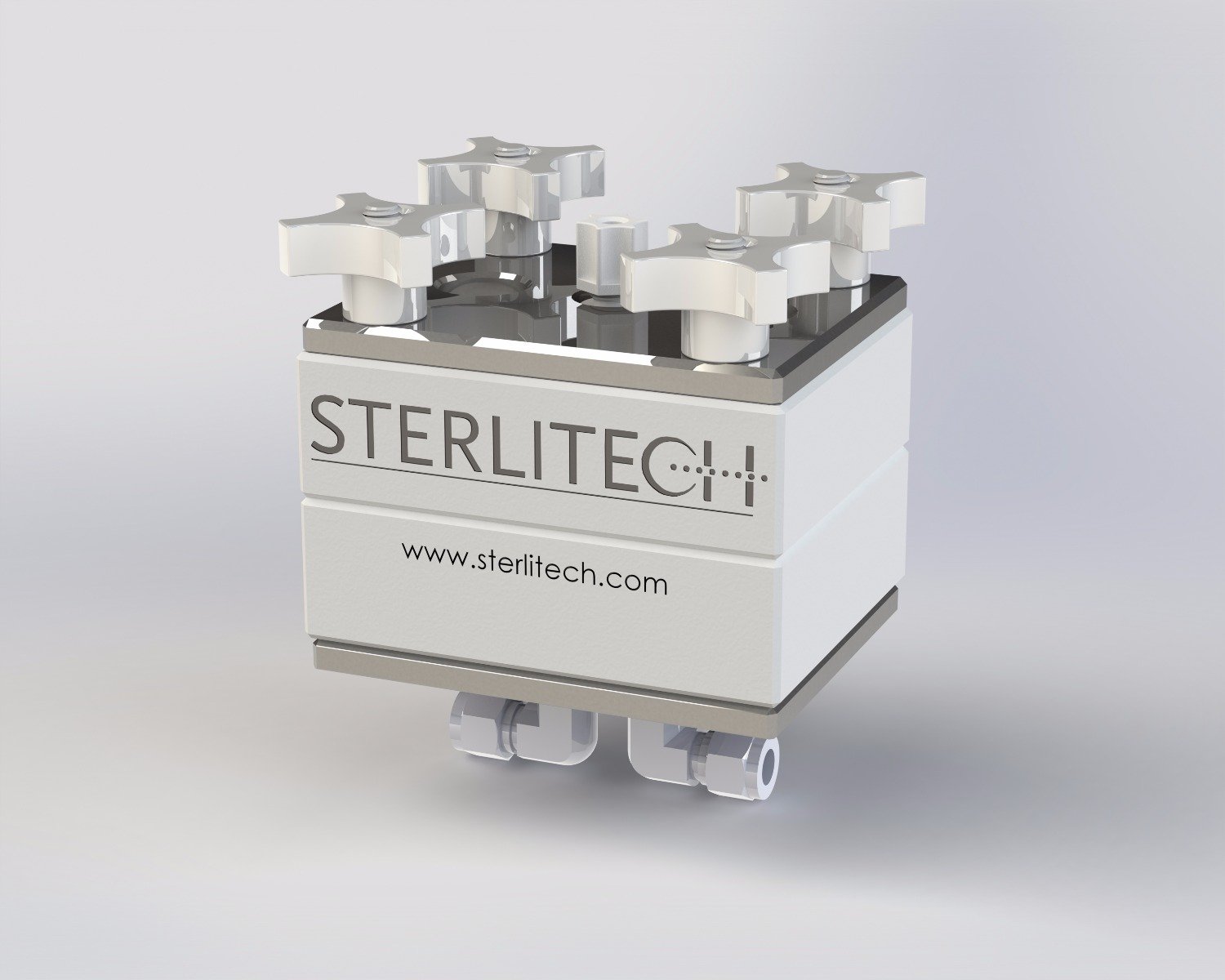
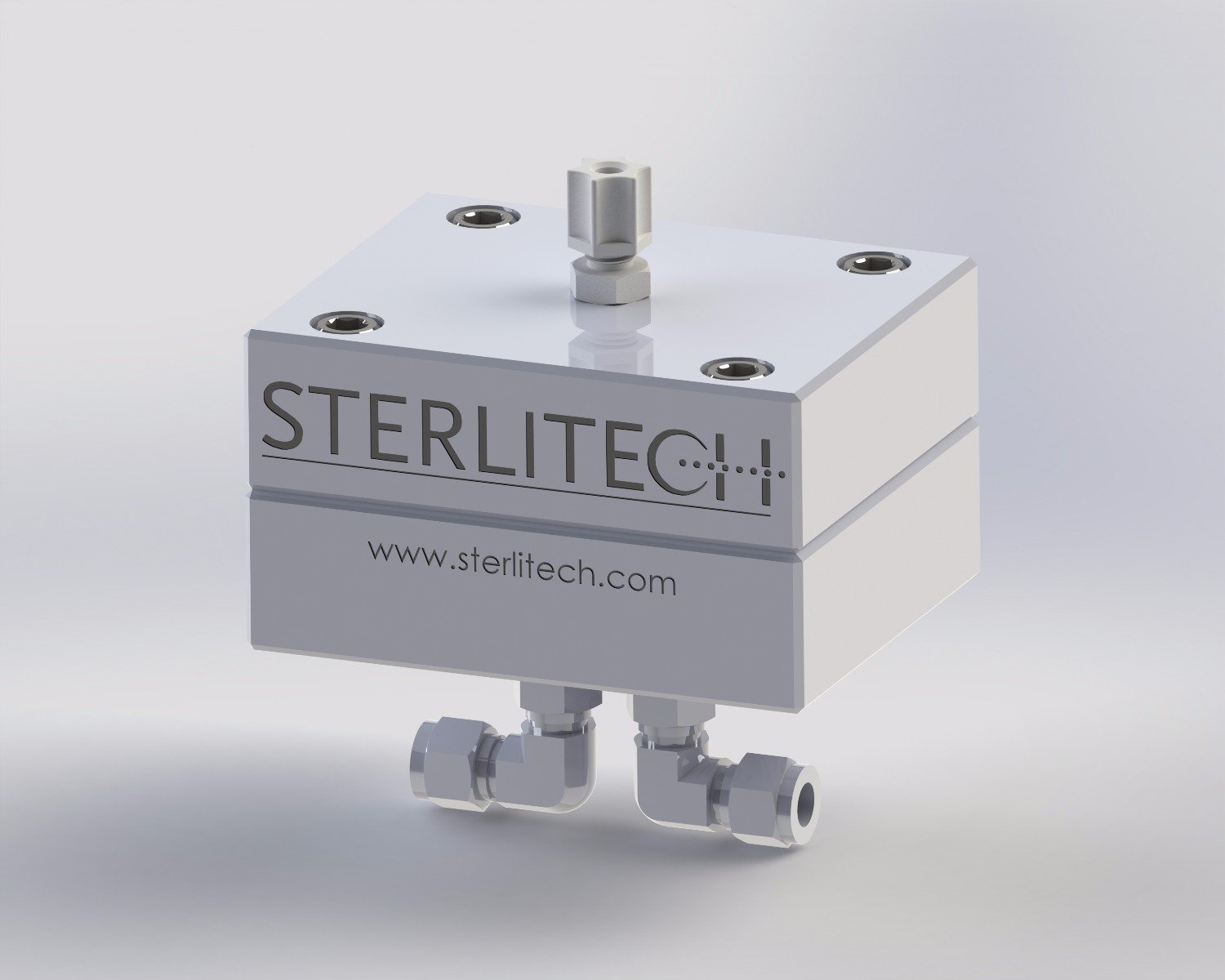
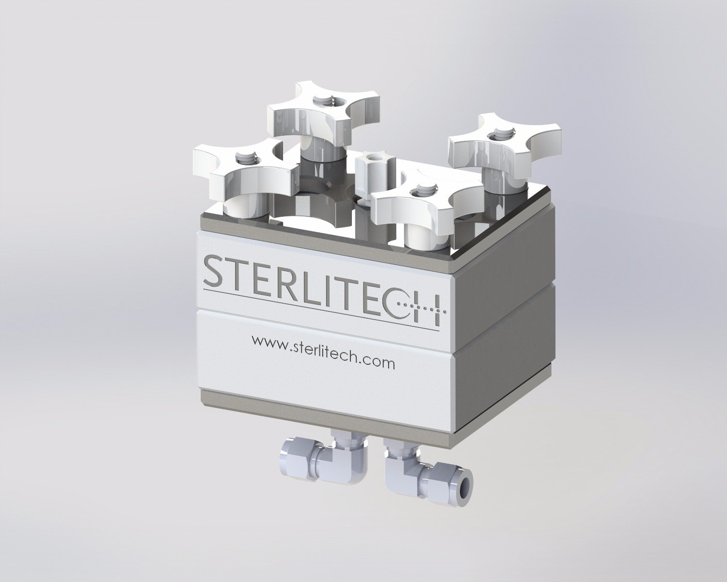
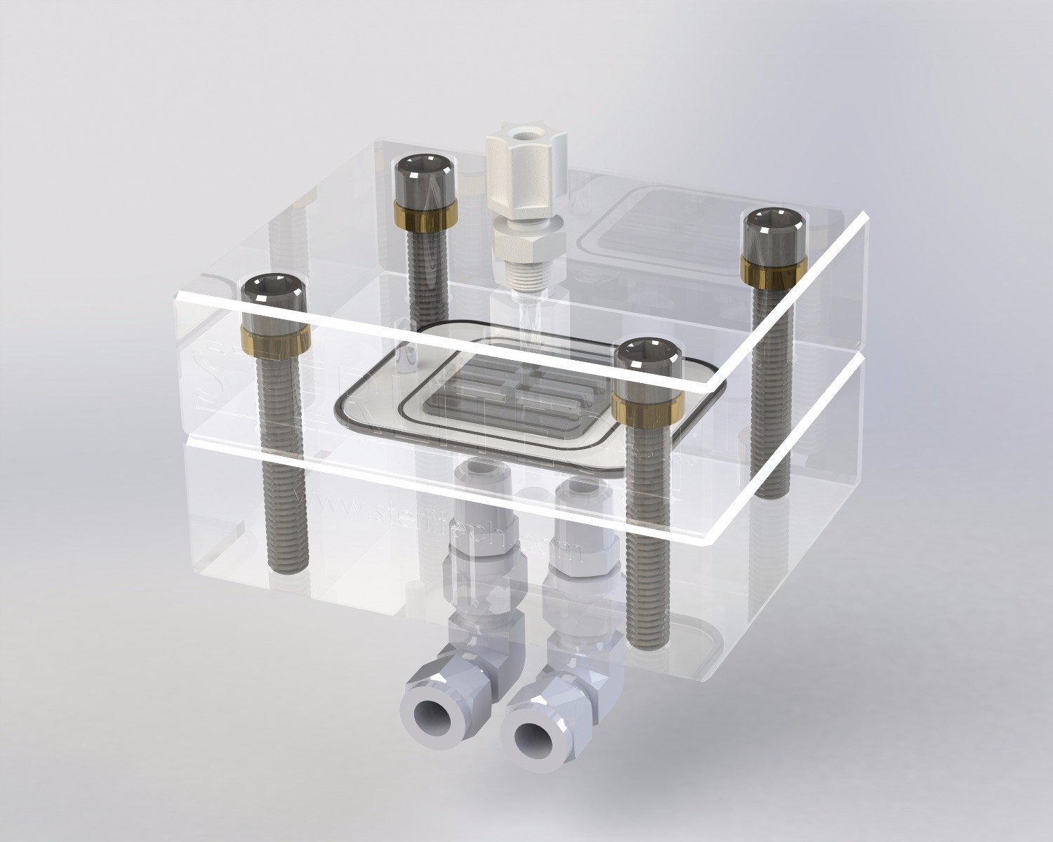
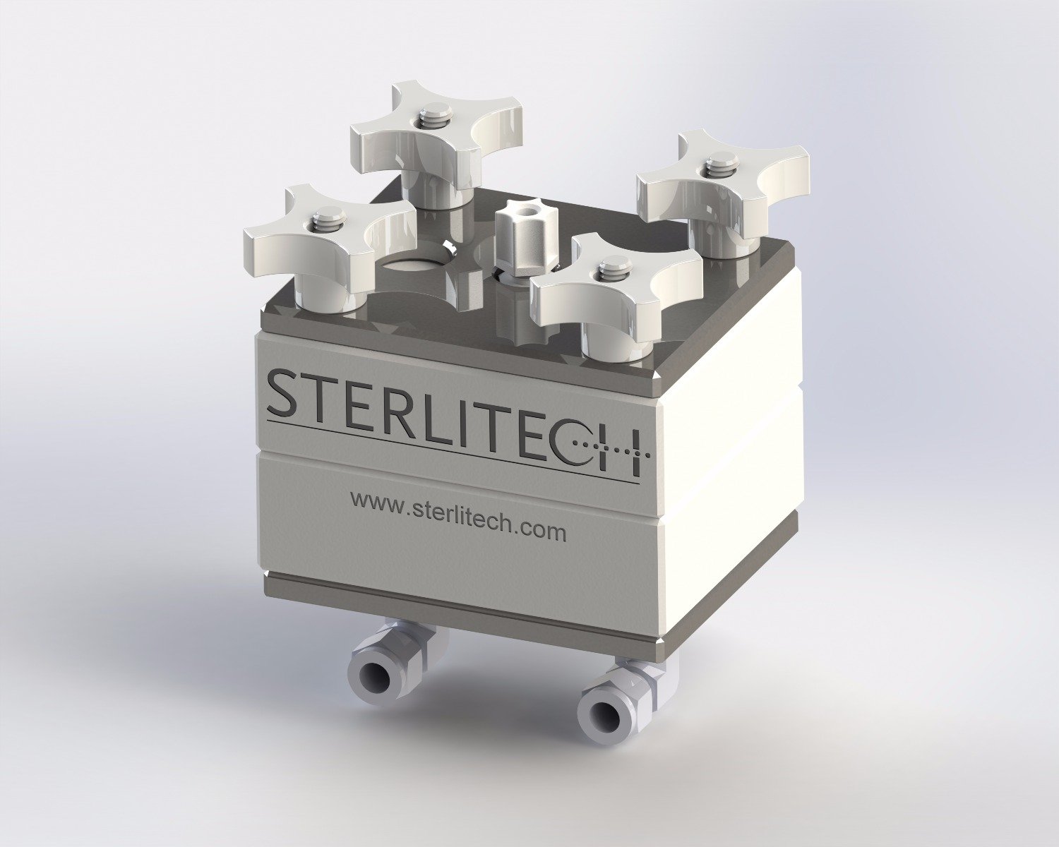
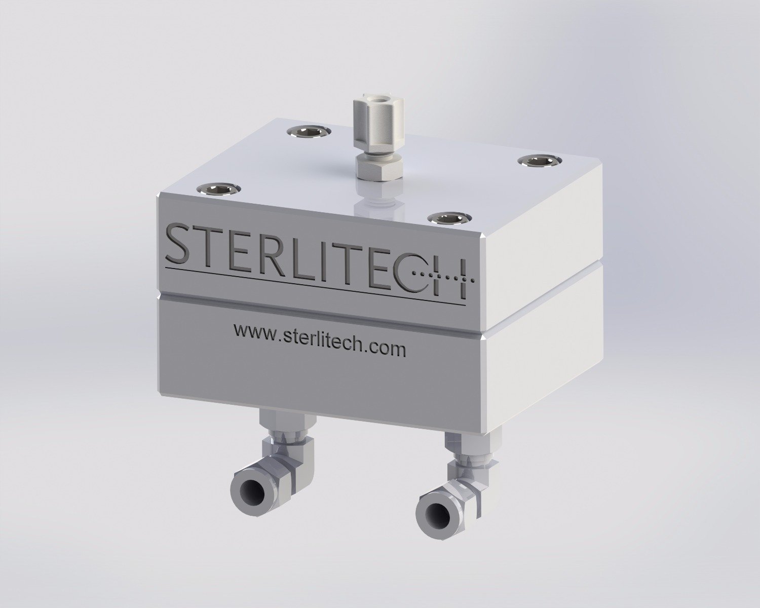
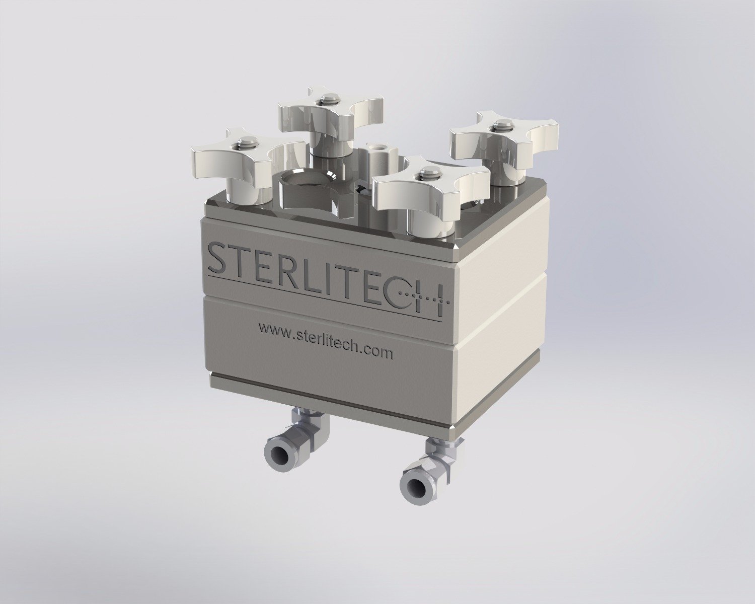
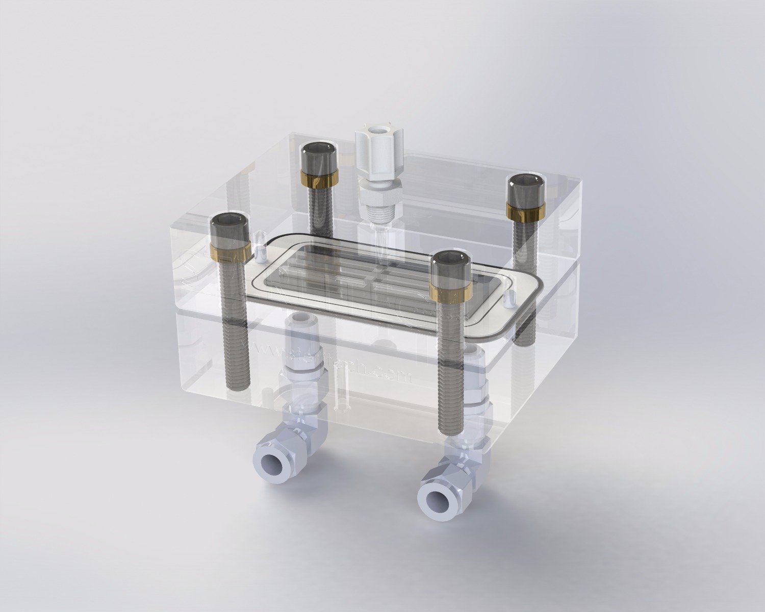
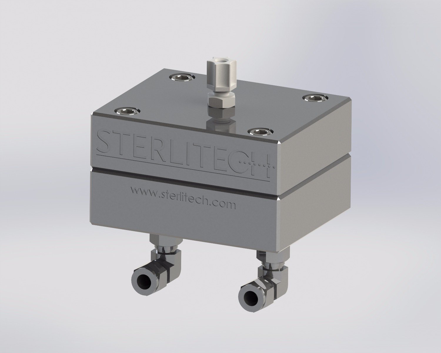
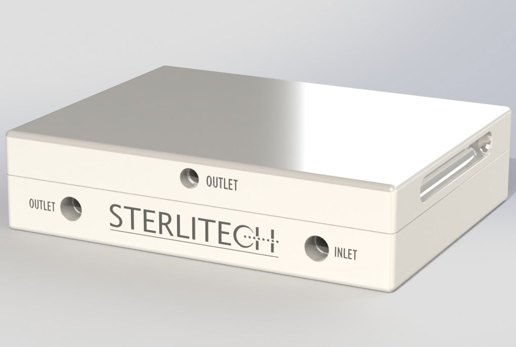
The CF042 cell is a bench-scale cross/tangential flow cell that provides fast and accurate performance data with minimal amounts of membrane, product, expense or time. Available in Delrin, Stainless Steel, or Hastelloy for high pressure operation and PTFE or Acrylic for low pressure operation. All cells are compatible with our kits, benchtop systems, and skid systems.
CF042 Cell Features and Benefits:
- Accepts polymeric flat sheet membrane coupons
- Mimics both laminar or turbulent flow conditions
- Provides fast and accurate performance data
- Offers judicious membrane use with small membrane active area
Interested in learning how to operate our membrane process equipment? Check out our MPD channel to watch videos now!
| SKU | Product Name | Material Type | Price | ||
|---|---|---|---|---|---|
 | 1160238 | CF042 Cell Assembly, Crossflow, Acetal Copolymer (Delrin) (CF042D) | Delrin Acetal | $1,110.51 | |
 | 1160236 | CF042 Cell Assembly, Crossflow, 316 SS (CF042SS) | 316 SS | $4,160.03 | |
 | 1160166 | CF042 Cell Assembly, Crossflow, Acrylic (CF042A) | Acrylic | $1,354.24 | |
 | 1160254 | CF042 Cell Assembly, Crossflow, PTFE (CF042P) | PTFE Cell | $1,225.81 | |
 | 1160266 | CF042 Cell Assembly, Crossflow, Hastelloy (CF042H) | Hastelloy™ | $12,190.43 |
Accessory


Applications
Cross/tangential flow test cells are typically used in membrane applications such as :
- Biological or biopharmaceutical processing
- Concentration of fruit juices and extracts
- Food and beverage processing
- Desalination of brackish water or seawater
- Purification of rinse water in electroplating tanks
- Municipal or industrial water and wastewater purification
Specifications
Specifications by Material:
| Product Family | Innovator | Explorer | Developer | |||||||||
|
|
|
|
|
|
|
|
|
|
|
|
|
|
|---|---|---|---|---|---|---|---|---|---|---|---|---|
|
Material |
Acetal (Delrin) |
316 Stainless Steel |
Virgin PTFE |
Acrylic |
Acetal (Delrin) |
316 Stainless Steel |
Virgin PTFE |
Acrylic |
Hastelloy™ |
316 Stainless Steel |
Acrylic |
Hastelloy™ |
|
Maximum Bolts Torque Setting (in-lbs) |
60 |
NA |
15 |
45 |
60 |
NA |
15 |
45 |
70 |
NA |
45 |
70 |
|
Maximum Fittings Torque Setting (in-lbs) |
25 |
25 |
25 |
25 |
25 |
25 |
25 |
25 |
25 |
25 |
25 |
25 |
|
Max Pressure |
69 bar |
69 bar |
27.6 bar |
27.6 bar |
69 bar |
69 bar |
27.6 bar |
27.6 bar |
69 bar |
69 bar |
15.2 bar |
69 bar |
|
Max Temperature |
82°C |
150°C |
260°C |
88°C |
82°C |
150°C |
260°C |
88°C |
150°C |
150°C |
88°C |
150°C |
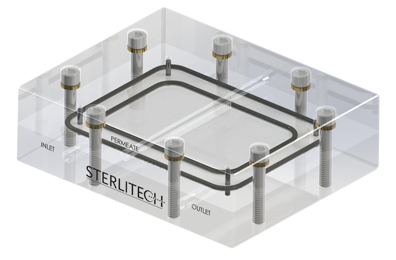
General Cross Flow Cell Specifications:
| CF016 | CF042 | Sepa | |
|---|---|---|---|
| Active Membrane Area | 20.6 cm2 (3.2 in2) | 42 cm2 (6.5 in2) | 140 cm2 (22 in2) |
| Hold-Up Vol. | 13 mL (0.44 oz) | 17 mL (0.57 oz) | 70 mL (2.4 oz) |
| Connections |
Feed:1/4 in FNPT (base of cell) |
Feed:1/4 in FNPT (base of cell) |
Feed:1/4 in FNPT (base of cell) |
| Outer Dimensions |
12.7 x 10 x 8.3 cm (5 x 4 x 3.25 in) |
12.7 x 10 x 8.3 cm (5 x 4 x 3.25 in) |
16.51 x 21.3 x 5 cm (6.5 x 8.38 x 2.07 in) |
| Active Area Dimensions |
4.52 x 4.52 cm (1.78 x 1.78 in) |
9.207 x 4.572 cm (3.625 x 1.8 in) |
9.7 x 14.7 cm (3.81 x 5.78 in) |
| Slot Depth | 0.23 cm (0.09 in) | 0.23 cm (0.09 in) | 0.19 cm (0.075 in) |
| Slot Width | 39 mm (1.54 in) | 39 mm (1.54 in) | 95.3 mm (3.75 in) |
Documentation

Bench System - Sterlitech
Analog Skid - Sterlitech
 Frequently Asked Questions
Q: Why is the flat sheet membrane I'm using measuring a flux value less than the published flux value?
Flow characteristics for a spiral element and flat sheet membrane are significantly different and are really only comparable on a qualitative basis. Variability in the membrane manufacturing process, differences in water composition, test procedures, and test equipment, used in a factory, laboratory, or elsewhere, will impact water flux results.
Q: How do I optimize my crossflow test cell operating conditions for maximum permeate flux?
Most separations and flux through membranes are controlled by the nature of the fluid. For salt rejecting membranes (RO and NF), the dominant variables are operating pressure and osmotic pressure (a solute concentration-dependent property which reduces net operating pressure with increased solute concentrate).
Generally, permeate flux increases as the operating pressure increases; however, due to physical limitations of membranes, there is a practical limit above which increasing the operating pressure provides little or no flux increase. The fluid velocity across the membrane, controlled by the feed pump rate and concentrate control valve, is another important operating parameter. As the fluid velocity increases, the amount of mixing of the feed solution in the fluid layer directly above the membrane surface increases. The removal of fluid through the membrane (permeate) results in accumulation of rejected solutes in this layer, referred to as the boundary layer.
The accumulation of solutes in the boundary layer can contribute a significant resistance to permeate flux through the membrane and is often the factor most limiting permeate flux. Increasing the feed solution velocity across the membrane and using turbulence promoting foulant spacers, provides the optimal combination for boundary layer mixing to mitigate solute accumulation. However, considerations of energy expenditures and mechanical stress limitations of the membrane and the test cell system result in practical limitations for crossflow velocity. To find maximum permeate flux, we set the feed flow (and consequently the crossflow velocity) to a maximum practical rate and increase the operating pressure incrementally while monitoring the flux output.
Typically, a given operating pressure can be found that will yield maximum permeate flux specific to the feed solution and feed flow. If the feed is recirculated and the solute concentration changes, then the optimal operating pressure may change and typically decreases as solute concentration increases unless the osmotic pressure becomes significant. For systems operated with recirculating feed, it may be more optimal to operate at a pressure somewhat lower than the maximum pressure initially determined and may result in greater total permeate flux over time.
Q: Is there a difference in membrane rejection and permeate flux for a crossflow test cell operated continuously versus being operated in intervals?
Q. Is there a difference in membrane rejection and permeate flux for a crossflow test cell operated continuously versus being operated in intervals?
A. Yes, there may be a difference in membrane rejection and permeate flux, at least initially during the operating intervals. At startup, there is a period of membrane conditioning that occurs as a result of mechanical compression.
This conditioning influences the rejection and permeate flux and is to some extent reversible when the operating pressure is relieved.
Consequently, there is a period of membrane conditioning that occurs every time the system is restarted. For sufficiently long operating intervals, the rejection and permeate flux will approach those for continuous operation.
Q: What are the available materials of construction for the Sterlitech crossflow test cells?
The Sterlitech bench-scale crossflow test cells are available in a variety of materials to suit most applications:
- Stainless Steel
- PTFE
- HastelloyTM
- Delrin (natural acetal copolymer)
- Acrylic
Addtionally, there are a variety of available o-ring seals including Buna-N, EPDM, Viton, FEP encapsulated Viton, and FFKM (Markez).
Q: Can I operate a crossflow test cell without a foulant spacer?
Q. Can I operate a crossflow test cell without a foulant spacer?
A. Depending on the feed pressure and crossflow velocity, operating a crossflow test cell without a foulant spacer may cause the membrane to become wrinkled and damaged, and is not recommended.
Typically, a foulant spacer with the same thickness as the feed channel is used. A foulant spacer thinner than the feed channel can be used in combination with a shim (or shims) of appropriate thickness.
Q: Should I be concerned if the foulant spacer leaves an imprint on the membrane?
It is not uncommon for the foulant spacer to leave an imprint on the membrane and, in most cases, is not a cause for concern.
However, it is important to verify that the foulant spacer (or the foulant spacer and shim combination) is not thicker than the feed channel. If too thick of a foulant spacer is used, then it may cause damage to the membrane.
Q: How do I distinguish between the low foulant (34ml) feed spacer and the high foulant (68ml) feed spacer when I hold them in my hands?
Q. How do I distinguish between the low foulant (34ml) feed spacer and the high foulant (68ml) feed spacer when I hold them in my hands?
A. The low foulant has smaller squares and bends slightly easier. It feels lighter. It is not stiff like the medium foulant. The high foulant spacer has corragated ridges in it like cardboard. No holes.
Q: Is the 17mil low foulant spacer the same as the 17mil permeate carrier? Can the permeate carrier be used as a foulant spacer?
Q. Is the 17mil low foulant spacer the same as the 17mil permeate carrier? Can the permeate carrier be used as a foulant spacer?
A. No, the foulant spacer and the permeate carrier are not the same. The foulant spacer is designed to accommodate particulate in the feed stream and to enhance the crossflow action near the membrane surface. Since there is essentially no particulate in the permeate stream, the permeate carrier is optimized to provide maximum support to the membrane without concern for accommodating particulate. Consequently, the permeate carrier should not be used as a foulant spacer.
Q: In the instruction manual for the Sepa CF, mesh and tubular foulant spacers are mentioned. What is the difference?
Q. In the instruction manual for the Sepa CF, mesh and tubular foulant spacers are mentioned. What is the difference?
A. The 31 mil low foulant spacer and the 47mil medium foulant spacer have a mesh design with discrete openings.
The 65mil high foulant spacer has a tubular or corrugated, design without discrete openings.
The tubular design is less likely to be fouled by feed streams with elevated particle loading.
Q: How do I install/remove permeate fittings or other plastic NPT fittings?
Sterlitech recommends to install all plastic fittings by hand using PTFE tape. If a plastic NPT or compression fitting starts to leak during operational testing, tighten the fitting carefully until the leaking stops. Excessive tightening may break the fitting or damage other components.
If the fittings is broken and stuck in the cell top, use a spiral flute extractor bit or similar tool to release the portion of the fitting in the cell top. If the cell top becomes cracked from removal efforts, a replacement can be purchased.
Q: How do I calculate the Reynolds number for the feed flow in a crossflow test cell?
The Reynolds number is a dimensionless number that is related to the ratio of inertial forces to viscous forces experienced by a fluid for given flow conditions. The Reynolds number can be used to predict whether flow conditions result in a laminar or turbulent flow.
In theory, the cross section area of the test cell feed channel can be used to calculate the Reynolds number for the feed flow. In practice, it is very difficult to calculate the Reynolds number because of the complex geometry of the foulant spacer occupying the feed channel. There are empirical methods to estimate the Reynolds number by characterizing the relationship between feed flow and differential pressure.
Please contact us at [email protected] if you need assistance.
Q: What is GFD?
GFD is an abbreviation for gallons per square foot per day. It is a common unit of measure for membrane permeate flow.
Q: I have noticed that the flat sheet membranes come in sizes described as CF016, CF042, and Sepa CF. What are these sizes?
These membrane sizes are intended for use in the bench-scale crossflow test cells offered by Sterlitech. Please see list of flat sheet membranes we offer and their dimensions:
- HP4750 Stirred Cell: 47 mm (1.85") discs
- CF016 cell: 58 x 75mm (2.26 x 2.95") coupons
- CF042 cell: 56 x 115 mm (2.20 x 4.53") coupons
- Sepa CF cell: 140 x 190 mm (5.51 x 7.48") coupons
- CF047 circular cell: 47mm discs
- CF090 circular cell: 90 mm discs
Q: Could the filter cloth of industrial filters be used in the Sepa filtrations units, after cutting it to proper size?
Q. Could the filter cloth of industrial filters be used in the Sepa filtrations units, after cutting it to proper size?
A. The Sepa CF can potentially work for any media that can be fitted into the chamber.
One thing that could be an issue for some types of filter media is whether or not a sufficient seal is made between the O-ring and the media. For membranes, this is not a problem because membranes have a relatively smooth surface, which affords good mechanical seal when pressed together. A large fiber woven material, for example, may need to be modified or filled with some type of potting compound to level the surface in order to get a non-bypass seal.
Q: What are the torque settings for the CF042 and Sepa CF Cells?
Q: What are the torque settings for the CF042 and Sepa CF Cells?
A: Best practices for plumbing of polymer (Acrylic, Delrin, and PTFE cells) CF042 cells, include the use of PTFE tape properly installed on 1/4npt threaded coupling, and the use of a light coat of PTFE-based pipe thread sealant, then the coupling needs to be seated in the base of the cell using the following torque settings:
- Delrin- 60 inch pounds
- Acrylic -70 inch pounds
- PTFE -15 inch pounds OR until the fitting "shoulders" out on the base of the CF042 cell*
*extreme caution should be used to assure that the fitting is not started incorrectly (cross-threaded). In normal installation, the fitting should easily turn in several turns without tooling (by "hand") before using the torque wrench.
